Resistors, as their name implies, are designed to provide some desirable, or necessary, amount of resistance to current flow in a circuit. They can also be used to 'drop' voltage. As such they are the main elements used in circuit design to arrive at the desired current flows and voltages which work the circuit. Resistors do not generate electrical energy, but merely absorb it, which the resistor dissipates in the form of heat. The performance of a resistor is not affected by frequency, so it behaves the same way in both dc and ac circuits.
Resistors are specified by 1. resistance value in ohms; 2. tolerance as a percentage of the nominal value; and 3. power rating in watts. They are also categorized by the type of construction.
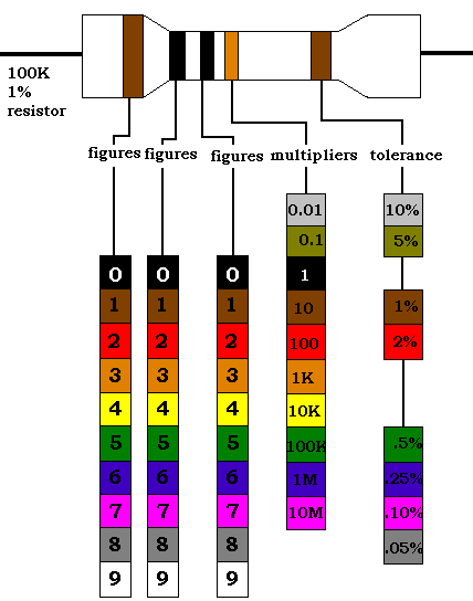
Resistance value and tolerance is normally indicated by a colour code consisting of four coloured rings, starting at or close to one end.
These are read as follows:
1st ring gives first digit.
2nd ring gives second digit.
3rd ring gives number of noughts(zeros) to put after first two didits.
The Universally adopted colour coding is:

Certain types of modern resistors of larger physical size may have letters and numbers indicate the numerical value and the following letter the multiplier, where:
E = *1 (multiplied by one)
K = *1000 (multiplied by thousand)
M = *1000000
A second letter then gives the tolerance:
M = 20% tolerance either side of the nominal value.
K = 10% tolerance either side of the nominal value.
J = 5% tolerance either side of the nominal value.
H = 2.5% tolerance either side of the nominal value.
G = 2% tolerance either side of the nominal value.
F = 1% tolerance either side of the nominal value.
The actual range of (nominal) resistance values to which resisistors are made is based on steps which give an approximately constant percentage change in resistance from one value to the next - not simple arithmetical steps like 1,2,3 etc. These are based on the preferred numbers:
1, 1.2, 1.5, 1.8, 2.2, 2.7, 3.3, 4.7, 5.6, 6.8, 8.2, 10, 12, 15, 18 etc
Thus, for example, a typical range of resistor values would be:
10, 12, 15, 18, 22, 27, 33, 39, 47, 56, 68, 82, and 100 ohms.
120, 150, 180, 220, 270, 330, 390, 470, 560, 680 and 820 ohms.
1, 1.2, 1.5, 1.8, 2.2, 2.7, 3.3, 3.9, 4.7, 5.6, 6.8, and 8.2 Kiloohms.
10, 12 etc Kilo ohms
1, 1.2 etc Kilo ohms
As regards tolerances, as a general rule resistors with a 10 percent tolerance are suitable for average circuit use. The actual resistance value of, say, a 1 kohm resistor would then be anything between 900 and 1100 ohms. For more critical work, such as radio circuits, resistors with a 5 percent tolerance would be preferred. Closer tolerances are not normally required, except for very critical circuits.
The physical size (or shape) of a resistor is no clue to its resistance value, but can be a rough guide to its power rating. Physical sizes range from about 4mm long by 1mm diameter up to about 50mm long and 6mm or more diameter. The former would probably have a power rating of 1/20th watt and the latter possibly 10 watts. More specifiacally, however, the power rating is related to type as well as size. A general rule which does not apply to power rating, however is that whilst this figure nominally represents a safe maximum which the resistor can tolerate without damage, it is usually best to operate a resistor well below its power rating - say at 50 percent rating - particularly if components are crowded on a circuit, or the circuit is enclosed in a case with little or no ventilation.
Maximum operating voltage may also be specified, but since this is usually of the order of 250 volts or more, this parameter is not important when choosing resistors for battery circuits. Resistors used on mains circuits must, however, have a suitable voltage rating.
Resistor types classified by construction are:
All resistors can be expected to undergo a change in resistance with age. This is most marked in the case of carbon-composition resistors where the change may be as much as 20 percent in a year or so's use. In the case of carbon-film and metallic film resistors, the change is seldom likely to be more than a few percent.
The genral effect of increasing frequency in ac circuits is to decrease the apparent value of the resistor, and the higher the resistor value the greater this change is likely to be. This effect is most marked with carbon-composition and wire-wound resistors (see below). Carbon-film and metal-film resitors all have stable high frequency characteristics.
